Chapter VI SHOCK EFFECTS OF SURFACE AND SUBSURFACE BURSTS
CHARACTERISTICS OF SURFACE AND SHALLOW UNDERGROUND BURSTS
INTRODUCTION
6.01 Surface and shallow underground bursts are defined as those in which either the fireball or the hot, high-pressure gases generated by the explosion intersect or break through the earth’s surface. In explosions of this type, part of the energy released is spent in producing a surface crater, whereas much of the remainder appears as air blast and ground shock. The greater the depth of the burst point below the surface, the smaller is the energy expended as air blast. The dimensions of the crater increase at first with increasing depth of burial of the weapon, pass through a maximum, and then decrease virtually to zero at still greater depths.
AIR BLAST
6.02 In a contact surface burst (§ 2.127 footnote) the incident and reflected air blast waves coincide immediately, forming a hemispherical shock front as shown in Fig. 3.34. The characteristics of the blastwave accompanying a reference (1 kiloton) explosion, as functions of the distance from ground (surface) zero (§ 2.34 footnote), can then be obtained from the curves given at the end of Chapter III. The cube root scaling law described there can be used to calculate the blast wave properties from a contact surface burst of any specified energy yield. When the burst occurs below the surface, the air blast arises partly from the ground shock transmitted through the surface into the air and partly from the release of the high-pressure gases produced in the explosion. At shallow burst depths the latter effect predominates but with increasing depth of burial it contributes less and less to the air blast. Furthermore, as the depth of burst is increased, the higher overpressures closer to surface zero fall off more rapidly than do the lower overpressures at greater distances. More information concerning the air blast from shallow underground explosions and the effect of yield and burst depth on the spatial distribution of the overpressure is given in § 6.80 et seq.
CRATER FORMATION
6.03 The mechanism of crater formation depends on the height or depth of the burst. For an explosion well above the surface but in which the fire ball intersects the ground (§ 6.08), a depression crater is formed as a result of the vaporization of considerable quantities of earth material. This material is sucked upward by ascending air currents resulting from the rising fireball and it eventually appears as fallout (Chapter IX). For bursts at or near (above or below) the surface, air blast plays a part in crater formation, in addition to vaporization. Surface material is then removed by being pushed, thrown, and scoured out. Some of this material falls back into the crater and most of the remainder is deposited around the edges to form the lip of the crater or is scattered as loose ejecta beyond the crater.
6.04 When the burst is at such a depth that surface vaporization and scouring by air blast are not significant, several other processes may contribute to the formation of a “throwout” crater. One is the crushing and fracture of the ground material by the expanding compressional (shock) wave. Another important mechanism is spalling, i.e., the separation of earth layers at the surface (§ 2.91). The spalled layers will fly upward and be deposited as ejecta beyond the crater or on the lip, or, for moderately deep burials, they will fall back into the crater itself. If the hot, high pressure gases formed by the explosion are not vented during the crushing and spalling phases, the expanding gases may force the confining earth upward; thus gas acceleration can contribute to crater formation, as described in § 2.92.
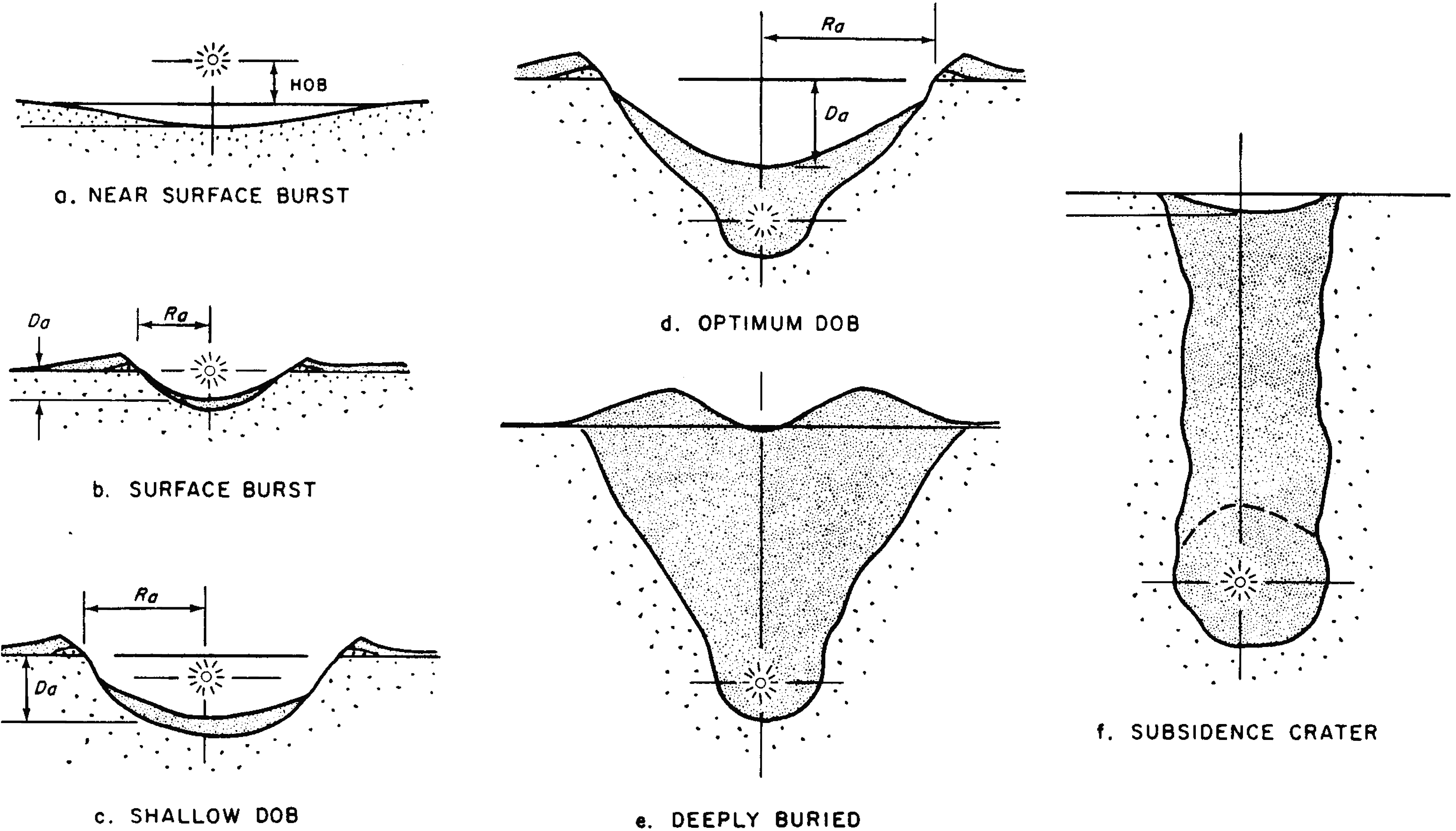
6.05 Finally, deeply buried explosions may lead to a subsidence crater, to a raised mound above the detonation point, or to no permanent displacement of the surface at all. If the collapse of the chimney containing broken and crushed material should reach the surface, a subsidence crater may be formed (§ 2.103). In strong earth material, such as hard rock, the chimney top may not reach the surface; surface displacement may then be only temporary. If bulking of the broken rock occurs, a surface mound may be formed above the chimney (Fig. 6.05).
6.06 The variations in the character of the crater as a result of the changes in the predominant mechanism of crater formation as the depth of burst (DOB) increases are illustrated in Figs. 6.06a through f. The depression crater in Fig. 6.06a is formed mainly by vaporization, with most of the removed material being carried away. In a contact (or near surface) burst, represented in Fig. 6.06b, scouring, etc., by an air blast also contributes to crater formation and some of the material removed falls back into and around the crater. At greater depths (Fig. 6.06c), spallation and gas acceleration become increasingly important and the dimensions of the crater increase. The crater reaches its largest size when gas acceleration is the predominant mechanism of formation, but even then a large quantity of material falls back (Fig. 6.06d). Finally, Figs. 6.06e and f show examples of bulking and subsidence, respectively, for deeper underground explosions.
6.07 Two more-or-less distinct zones in the earth surrounding the crater may be distinguished (see Fig. 6.70). First is the “rupture zone” in which stresses develop innumerable radial cracks of various sizes. Beyond the rupture zone is the “plastic zone” in which the stress level has declined to such an extent that there is no visible rupture, although the soil is permanently deformed and compressed to a higher density. Plastic deformation and distortion of soil around the edges of the crater contribute to the production of the crater lip. The thicknesses of the rupture and plastic zones depend on the nature of the soil, as well as upon the energy yield of the explosion and location of the burst point. If the earth below the burst consists of rock, then there will be a rupture zone but little or no plastic zone.
CRATER DIMENSIONS
6.08 For an explosion above the earth’s surface, appreciable formation of a vaporization (depression) crater will commence when the height of burst is less than about a tenth of the maximum fireball radius (§ 2.127). With decreasing distance from the surface, the dimensions of the crater vary in a complex manner, especially as the ground is approached, because of the change in the mechanism of crater formation. In general, however, the depth of the depression increases rapidly with decreasing burst height and the ratio of the depth to radius also increases. The dimensions of the crater increase with the explosion yield but the actual values depend on the soil characteristics.
6.09 For contact surface bursts, approximate values of the crater dimensions can be given. For a 1-kiloton nuclear explosion at the surface, the apparent radius of the crater in dry soil or dry soft rock is estimated to be about 60 feet. The radius at the crest of the lip will be 15 feet or so greater. The apparent depth of the crater is expected to be about 30 feet. In hard rock, consisting of granite or sandstone, the dimensions will be somewhat less. The radius will be appreciably greater in soil saturated with water, and so also will be the initial depth, to which structural damage is related. The final depth, however, will be shallower because of “hydraulic fill,” i.e., slumping back of wet material and the seepage of water carrying loose soil. All crater dimensions resulting from a surface burst of yield W kilotons are related approximately to those given above for a yield of 1-kiloton by the factor W03. For example, for a 100-kiloton explosion on the surface of dry soil, the radius of the crater may be expected to be roughly 60 x (100)0.3 = 240 feet, and the depth about 30 x (100)0.3 = 120 feet. Further information on crater dimensions will be found in § 6.72 et seq.
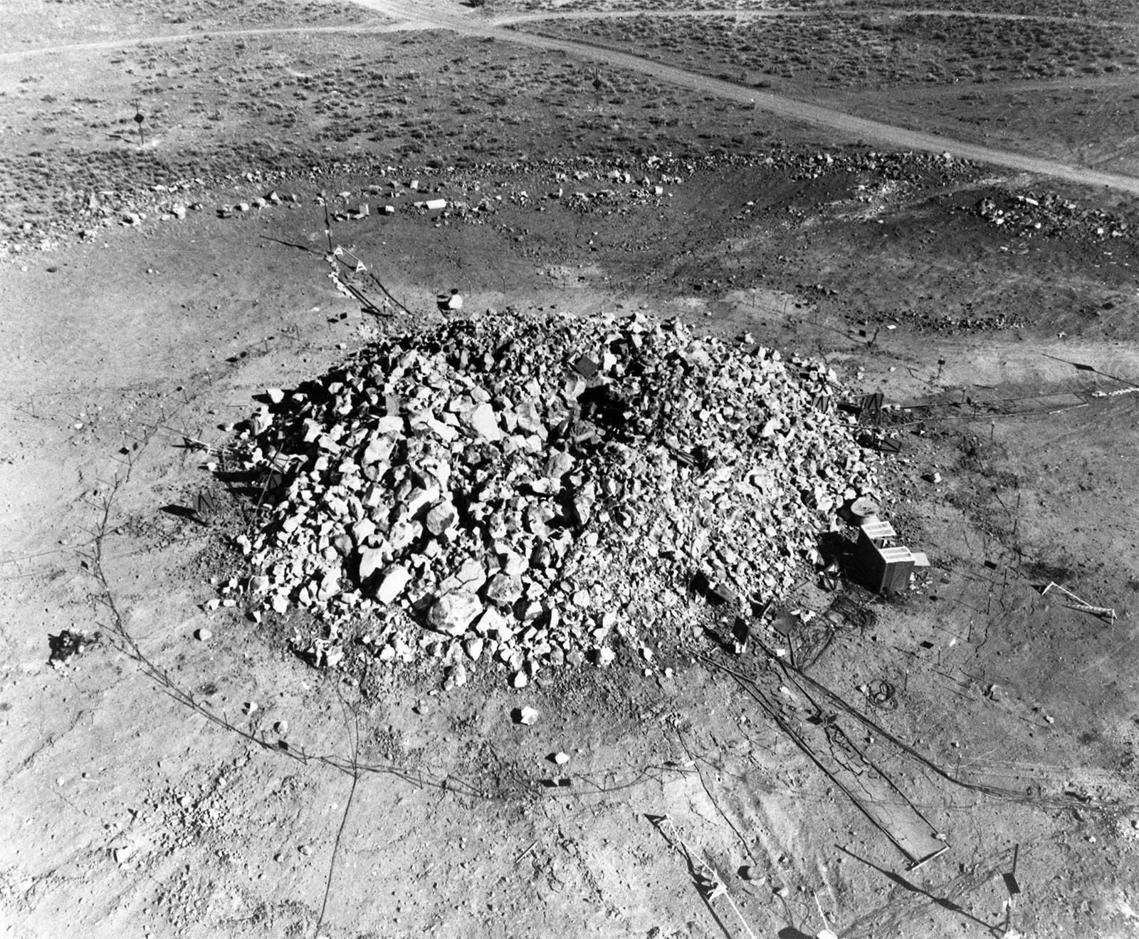
6.10 As the depth of burial is increased, the radius and depth of the crater also increase until maxima are reached; deeper burial then results in progressively smaller craters. These maximum values of radius and depth for a given yield are termed “optimum” (Fig. 6.06d) and depths of burial for optimum crater radius and for optimum crater depth are roughly equal. A photograph of a crater formed at the optimum burst depth is shown in Fig.
6.10 For a 1-kiloton weapon, the deepest crater possible, namely, 100 feet, is produced when the burst point is 120 feet below the surface; the radius of the crater at that depth will also be near its optimum, namely about 160 feet. Optimum values, like all crater dimensions, are approximately proportional to W0.3. Curves showing the variations of crater radius and depth with depth of burial in various media appear later in this chapter (§ 6.70 et seq.).

6.11 If the soil is saturated and the high water table is maintained after the detonation, the crater dimensions will change with time. Slumping of the crater sides will continue until a stable condition exists for the material. It can be expected that the sides of very large craters will ultimately slump until their slopes decrease to 10 to 15 degrees. As a result, the craters will become shallower and broader. In weak saturated soil with a very high water table, slumping occurs immediately. If the soil is stronger and the water table not too high, there is a time lag in the slumping which may be a matter of hours in sands and months in clay soils. Examination of craters in coral from high-yield bursts at the Eniwetok Proving Grounds has shown that the inward rush of water carries material which would normally constitute the crater lip into the bottom of the crater.
GROUND SHOCK
6.12 A nuclear explosion on or near the surface produces a ground shock in two primary ways, each of which sets the earth in motion; they are (I ) by direct coupling of explosive energy to the ground in the neighborhood of the crater, and (2) by pressure of the air blast wave as it runs over the earth’s surface. A random type disturbance is often superimposed on the ground motion resulting from these shocks (§ 6.82) but only the latter will be considered here. Each kind of ground shock (or pressure) is transmitted through the earth downward and outward. The direct ground shock contributes to the formation of the crater and the fracture and plastic zones immediately around it. The air blast pressure, called “airslap,” is the source of most of the stress on underground structures beyond the crater area when the burst point is not too deep.
6.13 Although shock waves transmitted through the earth may be greatly complicated and distorted by the presence of geological inhomogeneities, certain regularities tend to be found. Airslap, for example, almost always results in a single movement downward followed by a slower, partial relaxation upward; in some soils residual permanent compression after airslap is measurable and significant. The amount of earth motion depends on the air blast overpressure, the positive phase duration, and the character of the soil. Close to the surface, airslap motion is initially abrupt, similar to the rise of pressure in the air shock, but it becomes more gradual with increasing depth.
6.14 In those regions where the air blast wave front is ahead of the direct ground shock front at the surface, the situation is described as being “super seismic;” that is to say, the air blast wave is traveling at a speed greater than the speed of sound (or seismic velocity) in the earth. The ground motion near the surface is vertically downward, but it becomes increasingly outward, i.e., radial, from the burst point at greater depths below the surface.
6.15 On the other hand, when the air blast front lags behind the shock front transmitted directly through the ground, the ground wave is said to “outrun” the air blast. The airslap then causes the ground surface at locations ahead of it to undergo a characteristic outrunning motion, generally consisting of two or three cycles of a damped, i.e., decreasing, undulation with the first motion usually upward. Since the air blast overpressure decreases with increasing distance from surface zero, so also does the outrunning motion. If the air blast wave reaches the observation point while the outrunning surface motion is still underway, the airslap motion will be superimposed on the undulations.
6.16 At locations close to the burst, the air blast usually travels faster than the direct ground shock. The superseis mic condition then prevails and the first ground motion is determined essentially by the airslap. At greater distances, the air blast weakens and its velocity decreases significantly, but the ground shock velocity, which is approximately the same as the sesimic velocity, does not decrease very much. Hence, the ground shock front moves ahead and outrunning becomes the dominant factor in ground motion. At still greater distances from surface zero, the effect of airslap disappears or it is so weak that it merges with the direct ground shock without causing any outrunning motion. The phenomena described above are strongly influenced by the seismic velocities in the ground down to consider able depths.
6.17 The strength of the shock wave in the ground decreases with increasing distance from the explosion, and at large distances it becomes similar to an acoustic (or seismic) wave. In this region the effects of underground shock produced by a nuclear explosion are somewhat similar to those of an earthquake of low intensity. However, the evidence to date indicates that underground explosions do not cause earthquakes, except for minor aftershocks within a few miles of the burst point (§ 6.20 et seq.).
6.18 The effect of ground shock pressure on an underground structure is somewhat different in character from that of air blast on a structure above the ground. In the latter case, as explained in Chapter IV, the structure experiences something like a sudden blow, followed by drag due to the blast wind. This type of behavior is not associated with underground shock. Because of the similarity in density of the medium through which a ground shock wave travels and that of the underground structure, the response of the ground and the structure are closely related. In other words, the movement (acceleration, velocity, and displacement) of the underground structure by the shock wave is largely determined by the motion and containing action of the ground itself. This fact has an important influence on the structural damage associated with both surface and underground explosions. Damage criteria are outlined in§ 6.28 et seq. and are discussed more fully in § 6.90 et seq.
DEEP UNDERGROUND BURSTS1
GROUND SHOCK
6.19 In a fully-contained deep underground explosion there would be little or no air blast. Much of the energy is expended in forming the cavity around the burst point and in melting the rock (§ 2.102), and the remainder appears in the form of a ground shock wave. As this shock wave moves outward it first produces a zone of crushed and compressed rock, somewhat similar to the rupture zone associated with crater formation (Fig. 6.70). Farther out, where the shock wave is weaker, the ground may become permanently distorted in the plastic (deformation) zone. Finally, at considerable distances from the burst point, the weak shock wave (carrying less than 5 percent of the explosion energy) becomes the leading wave of a series of seismic waves. A seismic wave produces a temporary (elastic) displacement or disturbance of the ground; recovery of the original position, following the displacement, is generally achieved after a series of vibrations and undulations, up and down, to and fro, and side to side, such as are typical of earthquake motion.
AFTERSHOCKS AND FAULT DISPLACEMENTS
6.20 Many of the aftershocks associated with a deep underground explosion appear to be directly related to the postdetonation phenomena of cavity collapse and chimney growth (§ 2.103). Some aftershocks, however, originate a few miles beyond the region involved in the development of the chimney. These aftershocks are generally considered to result from small movements along pre existing fault planes2 and to represent the release of natural strain (deformation) energy. For explosions of high energy yields aftershocks may continue, although at a reduced rate, for many days after the chimney has formed.
6.21 The 1.1-megaton BENHAM test was conducted at a depth of 4,600 feet in tuff (§ 2.104) at the Nevada Test Site on December 19, 1968. During the period of six weeks following the detonation, some 10,000 weak aftershocks were detected, nearly all within 8 miles of the explosion point. Of these, 640 aftershocks were chosen for detailed study and their locations are shown by the small crosses in Fig. 6.21. The thin lines indicate positions of known faults and the thick lines show approximately where fault displacements were observed at the surface. It is apparent that a large number of the aftershocks occurred along a north-south line, which is the general direction of the known faults. Many of these aftershocks presumably occurred along hidden faults or other geological discontinuities parallel to the faults.

6.22 As may be seen from Fig. 6.21, most of the ground displacements in the vicinity of the BENHAM explosion occurred along or near pre-existing fault lines. The maximum vertical displacement was 1.5 feet, at locations 1.5 and 2.5 miles north of the burst point. Larger displacements have occurred in some instances, but vertical displacements of the surface along or near fault lines have been mostly less than a foot. These displacements, although not continuous, may extend for a distance of several miles. For the same (or similar) conditions, the linear extent of displacement is roughly proportional to the yield of the explosion.
6.23 A rough rule of thumb has been developed from observations at the Nevada Test Site. According to this rule, displacement along a fault line may occur only if the distance (in feet) from surface zero is less than about 1000 times the cube root of the energy expressed in kilotons of TNT equivalent. Thus, for a 1-megaton (1000-kiloton) detonation, displacement would be expected only if the fault lines were within a distance of roughly 1000 x (1000)⅓ = 1000 × 10= 10,000 feet (about 2 miles). In other words, fault lines that are nowhere closer than 2 miles from a 1-megaton deeply buried explosion would not be significantly affected. However, if any part of the fault line is within 2 miles of the detonation site, the actual displacement may be observed along that fault line at a greater distance.
UNDERGROUND EXPLOSIONS AND EARTHQUAKES
6.24 Fear has been expressed that deep underground nuclear explosions of high energy might stimulate natural earthquakes, but there is no evidence that such is the case. The “hypocenter” or “focus” of an aftershock of an earthquake is the point below the surface where motion, e.g., slippage at a fault, responsible for the observed disturbance originated. The focal depths, i.e., the depths of the hypocenters below the earth’s surface, of the aftershocks that follow deep underground tests in Nevada have ranged from zero to roughly 4 miles, with most depths being between 0.6 and 3 miles. Natural earthquakes in the same area, however, have considerably greater focal depths. Hence, it seems unlikely that a nuclear explosion would stimulate a natural earthquake.
6.25 A statistical study has been made of the occurrence of earthquakes in a circular region of 535 miles radius around the Nevada Test Site to deter mine the possible effects of underground explosions. During a period of 104 hours preceding September 15, l961, when an extensive series of underground tests was initiated at the Nevada Test Site, 620 earthquakes were recorded. After December 19, 1968, the date of the high-yield BENHAM event, by which time 235 underground tests had been conducted, 616 earthquakes were observed in a 104-hour period. There thus appears to be no indication that underground tests have resulted in any significant change in the occurrence of earthquakes in the Nevada area.
6.26 Two high-yield underground nuclear explosions on Amchitka Island, in the Aleutian Island chain, are of special interest because the island is located in one of the earth’s most seismically active regions. The MILROW device, with a yield of about 1 megaton TNT equivalent, was detonated on October 2, 1969 at a depth of 4,000 feet. The explosion was followed by a few hundred small, separate aftershocks which were apparently related to deterioration of the explosion cavity. This aftershock activity decreased at first but later increased sharply and then terminated within a few minutes of a larger, complex multiple event at 37 hours after the burst. The simultaneous formation of a surface subsidence indicated that complete collapse of the cavity occurred at this time. Subsequently, 12 small aftershocks of a different type, ten of which were detected within 41 days of the explosion, were observed during a period of 13 months. Two of these events were close to the explosion region and most of the others originated at or near the Rifle Range Fault, some 2 or 3 miles away. They were attributed to underground structural adjustments following the explosion.
6.27 A more stringent test was provided by the CANNIKIN event on November 6, 1971 when a nuclear weapon with a yield described as being “less than 5 megatons” was exploded at a depth of 5,875 feet below the surface of Amchitka Island. The number of initial, small aftershocks arising from cavity deterioration was larger than after the MILROW test, but otherwise the phenomena were similar. Cavity collapse, immediately preceded by considerable activity, occurred 38 hours after the explosion. During the next 23 days, 21 earth tremors were detected and one more occurred more than 2 months later, but there were no others during the next year. Of these disturbances, five were not clearly related to the explosion cavity or to known faults. The hypo centers, as well as those of the tremors following MILROW, were all less than 4.5 miles deep, compared with depths exceeding 12 miles for essentially all natural earthquakes in the area. Furthermore, there was no evidence of any increase in the frequency of such earthquakes in the sensitive Aleutian Islands region following the MILROW and CANNIKIN events.
DAMAGE TO STRUCTURES
SURFACE AND SHALLOW UNDERGROUND BURSTS
6.28 For a nuclear burst at a moderate height above the ground the crater or depression formed will not be very deep, although it may cover a large area. Shallow buried and semiburied structures near ground zero will be damaged by this depression of the earth. For deep underground structures, ground shock may be the primary factor causing damage, but its effects are principally important to people and equipment within the structures. As far as structures above ground are concerned, the range of damage will depend upon the characteristics of the blast wave in air, just as for an air burst (see Chapter V). The area affected by air blast will greatly exceed that in which damage is caused by both direct and induced shock waves in the ground. In the event of a contact or near-surface burst, the situation is similar to that in a shallow underground burst, as described below.
6.29 The damage criteria associated with shallow underground (and contact surface) bursts, especially in connection with buried structures, are difficult to define. A simple and practical approach is to consider three regions around surface zero. The first region is that of the true crater, which is larger than the apparent (or observable) crater (§ 6.70). Within this region there is practically complete destruction. The depth at which underground structures directly beneath the crater will remain undamaged cannot be clearly defined. This depth is dependent upon the attenuation of pressure and ground motion in the material.
6.30 The second region, which includes the rupture and plastic deformation zones, extends roughly out as far as the major displacement of the ground. In some materials the radius of this region may be about two and one-half times the radius of the (apparent) crater. Damage to underground structures is caused by a combination of direct ground shock and shock induced in the ground by air blast. Damage to doors, air intakes, and other exposed elements may be expected from direct air blast. The actual mechanism of damage from these causes depends upon several more-or-less independent factors, such as size, shape, and flexibility of the structure, its orientation with respect to the explosion, and the soil characteristics (§ 6.90 et seq.).
6.31 Along with underground structures, mention may be made of buried utility pipes and tunnels and subways. Long pipes are damaged primarily as a result of differential motion at the joints and at points where the lines enter a building. Failure is especially likely to occur if the utility connections are made of brittle material and are rigidly attached to the structure. Although tunnels and subways would probably be destroyed within the crater region and would suffer some damage in the plastic zone, it appears that these structures, particularly when bored through solid rock and lined to minimize spalling, are very resistant to underground shock.
6.32 In the third region, beyond the plastic zone, the effects of ground shock are relatively unimportant and then air blast loading becomes the significant criterion of structural damage. Strong or deeply buried underground structures will not be greatly affected, but damage to moderately light, shallow buried structures and some utility pipes will be determined, to a great extent, by the downward pressure, on the ground, i.e., by the peak overpressure of the air blast accompanying the surface or subsurface burst. Structures which are partly above and partly below ground will, of course, also be affected by the direct air blast.
DEEP UNDERGROUND BURSTS
6.33 The ground shock wave from a deep (or moderately deep) underground nuclear explosion weakens into a train of seismic waves which can cause appreciable ground motion at considerable distances from surface zero. The response of aboveground structures of various types to this motion can be predicted with a considerable degree of certainty. The procedures for making these predictions will not be described here (see § 6.90 et seq. ), but some of the general conclusions are of interest.
6.34 It is natural for buildings, bridges, and other structures to vibrate or oscillate to some extent. Apart from earthquakes and underground detonations, these vibrations can result from high winds, from sonic booms, and even from vehicles on a nearby street or subway. Every structure and indeed every element (or component) of a structure has many natural periods of vibration. For the majority of common structures, the most important of these periods is usually the longest one. This is generally a second or two for a tall building (10 to 20 stories) and a fraction of a second for a short one. Unless the structure has previously suffered significant damage, the natural periods of vibration do not change very much regardless of the source of the disturbance that starts the vibration.
6.35 The ground motion caused by a distant underground explosion (or an earthquake) contains vibrations of many different periods (or frequencies) and widely varying amplitudes. The waves of shorter periods (higher frequencies) tend to be absorbed by the ground more readily than those of longer periods (lower frequencies). Consequently, the greater the distance from the explosion, the larger is the fraction of seismic energy in ground vibrations with longer periods.
6.36 As a result of the effect called “resonance,” a structure tends to respond, e.g., vibrate, most readily to ground motion when the period of the latter is equal or close to one of the natural periods of vibration, especially the principal (longest) period, of the structure. Because the ground motion from an underground burst (or an earthquake) is so complex, at least one of the natural periods of the structure will be near to a period in the ground motion. All structures may thus be expected to respond to some extent to the ground motion from a distant underground explosion. If the response is more than the structure is designed to accept, some damage may occur.
6.37 With increasing distance from an explosion of specified yield, the seismic energy decreases, but a larger fraction of the available energy is present in the ground vibrations with longer periods. Furthermore, as already seen, tall buildings have longer vibration periods than shorter ones. As a result of these factors, the response of any structure decreases with increasing distance from an underground explosion, but the decrease is relatively less for the longer vibration periods, i.e., for tall buildings, than for the shorter periods, i.e., short buildings.
6.38 As might be expected, the response of any structure at a given distance from the burst point increases with the explosion energy yield. However, the increase is greater for longer than shorter vibration periods. Consequently, with increasing energy yield, the response of a tall building will increase more than that of a short building at the same distance from the explosion.
6.39 The foregoing generalizations, based on Nevada Test Site experience, imply that at greater distances from underground explosions of high energy yield there should be a tendency for a larger proportion of the seismic energy to appear in ground motion of longer periods. As a consequence, the responses of high-rise buildings, e.g., nine or more stories, with their longer vibration periods, are of special interest at greater distances from underground nuclear explosions of high yield. At shorter distances, where more seismic energy is available, both tall and short buildings could exhibit a significant response.
6.40 Tall buildings in Las Vegas, Nevada, more than 100 miles from the area where high-yield nuclear tests were conducted, have been known to sway in response to the ground motion produced by underground explosions, just as they do during mild earthquakes or strong winds. No damage, which could be definitely attributed to such explosions, however, was recorded in these structures prior to the HANDLEY event, with a yield somewhat greater than 1 megaton, on March 26, 1970. There was no structural damage in Las Vegas on this occasion, but nonstructural damage was reported as disturbance of ornamental blocks on one building and a cracked window in another, which could be readily repaired. There are no tall structures closer to the Nevada Test Site than those in Las Vegas, but low rise buildings nearer to the test area have experienced minor nonstructural damage, as was to be expected.
CHARACTERISTICS OF UNDERWATER BURSTS
SHOCK WAVE IN WATER
6.41 The rapid expansion of the hot gas bubble formed by a nuclear explosion underwater (§ 2.86) results in a shock wave being sent out through the water in all directions. The shock wave is similar in general form to the blast wave in air, although it differs in detail. Just as in air, there is a sharp rise in overpressure at the shock front. In water, however, the peak overpressure does not fall off as rapidly with distance as it does in air. Hence, the peak values in water are much higher than at the same distance from an equal explosion in air. For example, the peak overpressure at 3,000 feet from a 100-kiloton burst in deep water is about 2,700 pounds per square inch, compared with a few pounds per square inch for an air burst. On the other hand, the duration of the shock wave in water is shorter than in air. In water it is of the order of a few hundredths of a second, compared with something like a second or so in air.
6.42 The velocity of sound in water under normal conditions is nearly a mile per second, almost five times as great as in air. When the peak pressure is high, the velocity of the shock wave is greater than the normal velocity of sound. The shock front velocity becomes less at lower overpressures and ultimately approaches that of sound, just as it does in air.
6.43 When the shock wave in water strikes a rigid, submerged surface, such as the hull of a ship or a firm sea bottom, positive (compression) reflection occurs as in air (§ 3.78). However, when the water shock wave reaches the upper (air) surface, an entirely different reflection phenomenon occurs. At this surface the shock wave meets a much less rigid medium, namely the air. As a result a reflected wave is sent back into the water, but this is a rarefaction or tension, i.e., negative pressure wave. At a point below the surface the combination of the negative reflected wave with the direct positive wave produces a decrease in the water shock pressure. This is referred to as the “surface cut off.”
6.44 The idealized variation at a given location (or target) of the shock overpressure with time after the explosion at a point under water, in the absence of bottom reflections (§ 6.49), is shown in Fig. 6.44. The representation applies to what is called the “acoustic approximation” in which the initial shock wave and the negative reflected wave are assumed to travel at the same speed. After the lapse of a short interval, which is the time required for the shock wave to travel from the explosion to the given target, the overpressure rises suddenly due to the arrival of the shock front. Then, for a period of time, the pressure decreases steadily, as in air. Soon thereafter, the arrival of the reflected negative wave from the air-water surface causes the pressure to drop sharply, possibly below the normal (hydrostatic) pressure of the water. This negative pressure phase is of short duration.

6.45 The time interval between the arrival of the direct shock wave at a particular target in the water and that of the cutoff, signaling the arrival of the reflected negative wave, depends on the shock velocity and on the depth of burst, the depth of the target, and the distance from the burst point to the target. These three distances determine the lengths of the paths traveled by the direct (positive) and reflected (negative) shock waves in reaching the underwater target. If the latter is close to the surface, e.g., a shallow ship bottom, then the time elapsing between the arrival of the two shock fronts will be small and the cutoff will occur soon after the arrival of the shock front. A surface ship may then suffer less damage than a deeper sub merged target at the same distance from the explosion.
6.46 The idealized wave shape in Fig. 6.44 for the acoustic approximation is modified in practice, as illustrated in Fig. 6.46. When the shock intensity is strong, the reflection tends to overtake the shock wave because the shock wave sets in motion the water through which the following reflection (rarefaction) wave travels. Within a region near the air-water surface-the anomalous region-the initial shock wave may be strongly attenuated by overtaking rare factions, as shown at point A. At deeper levels (points B, C, D) differences in the paths traveled by primary and reflected waves may be too great to allow significant overtaking. Nevertheless, passage of the reflected wave through the disturbed water results in a less sharp surface cutoff than for the ideal acoustic approximation.

6.47 In deep water, when bottom (and other positive) reflections are not significant, the initial shock wave and the negative surface reflection are the most generally important features of the pressure disturbance arising from an underwater detonation. There are, however, several other effects which may be significant in some circumstances.
6.48 One group of such effects is associated with inhomogeneities of density, temperature, and salinity. Because shock wave speed depends on these nonuniform properties of the medium, underwater shock waves are often refracted, i.e., changed in direction, as well as reflected. This means that in some cases shock energy will be turned away from certain regions and will arrive at a target attenuated in strength. In other cases energy may be channeled or even focused into one part of the medium to produce a stronger than expected shock wave at some point remote from the detonation. Thus, in many areas the expected reduction of shock pressure by surface cutoff may be replaced by enhancement due to focusing.
6.49 Certain effects connected with the bottom may be important, particularly in shallow water. One of these is the bottom reflection of the primary shock wave. Unlike the reflection from the air, the bottom reflection is a compression wave and increases the pressure in regions it traverses. The pressure on the target now includes a positive reflected pressure in addition to the initial shock pressure and the negative (air-surface) reflected pressure. The characteristics of the overall pressure pulse, and hence the effect on an underwater target, will be dependent on the magnitudes and signs of the various pressures and the times of arrival at the target of the two reflected pressures. These quantities are determined by the three distances mentioned in § 6.45 and the water depth, as well as by the explosion yield and the nature of the bottom material.
6.50 When the bottom is rock or other hard material and the burst point is not too far above it, the bottom may contribute two compression waves; the first a simple reflection of the primary water shock, considered above, and the second a reradiation of energy transmitted a distance through the bottom material. The latter wave may become prominent if it can run ahead of the primary shock and then radiate energy back into the water. In this case the first motion observed at a remote station will be due to this bottom-induced wave.
6.51 In deep underwater nuclear explosions, the associated gas bubble may undergo two or three cycles of expansion and contraction before it collapses (§ 2.86 et seq.). Each cycle leads to distinct compression and rarefaction waves, called bubble pulses, which move outward through the water initially from the burst point and subsequently from the rising gas bubble.
6.52 Secondary underwater pressure pulses may be a consequence of the action of the reflected (negative) wave at the air-water surface. This wave moving downward can cause the temporary upward separation of water masses in a manner analogous to spalling in an underground burst (§ 2.91). When these water masses are brought together again by the action of gravity, the impact may set in motion a train of waves. The separation of water masses in this way is called spalling if the separated water flies into the air to produce a spray dome (§ 2.66) or “cavitation” if an underwater void (or cavity) forms.
AIR BLAST FROM UNDERWATER EXPLOSIONS
6.53 Although the particular mechanism will depend on yield and depth of burst, one or more air blast waves will generally follow an underwater nuclear detonation. In the first place, some energy of the primary shock wave in the water is transmitted across the water-air interface. This air shock remains attached to the water shock as it spreads out from the brust point. Second, if the scaled depth of burst, i.e., the actual depth of burst in feet divided by the cube root of the weapon yield W in kilotons, is less than about 35 feet/kilotons ⅓, the bubble vents directly into the atmosphere during its first expansion phase, thereby causing an air shock. Third, although deeper bursts will not vent, the spall or spray dome pushing rapidly upward into the air can cause an air shock. Beyond a scaled depth of approximately 150 feet/kilotons ⅓, however, the spray dome rises too slowly to cause an appreciable air shock. The second and third mechanisms produce air blast waves that lag far behind the primary water shock, but they can be identified underwater by airslap compression, similar to the airs lap effect of explosions at or near the ground surface (§ 6.12). Thus, an underwater target will always receive the primary water shock before the airslap, if any. Regardless of the generating mechanism, however, attenuation of air blast pressure with depth of burst below the water surface is rapid and follows a pattern similar to that shown in Fig. 6.81 for underground explosions.
SURFACE WAVES FROM UNDERWATER EXPLOSIONS
6.54 Underwater explosions generate relatively slow, outward-moving surface waves, which have certain recognizable characteristics. These waves, originating in the oscillations of the gas bubble as it breaks the surface, eventually form a train spreading in widening circles of steadily diminishing intensity around surface zero. The first surface wave near the burst is generally too steep to be sustained; consequently, it breaks into turbulent motion, consuming a large part of the original energy that would otherwise be available to the surface wave. Subsequently the train travels over deep water almost without further energy loss. The energy in this surface motion has been estimated to be between 2 and 5 percent of the weapon yield.
6.55 Certain characteristics of surface waves become more pronounced when the detonation occurs in shallow water rather than in deep water. Observation of the waves in the BAKER test (approximately 20-kilotons yield) at Bikini (§ 2.70) indicated that the first wave behaved differently from the succeeding ones; it was apparently a long, solitary wave, generated directly by the explosion, receiving its initial energy from the high-velocity outward motion of the water accompanying the expansion of the gas bubble. The subsequent waves were probably formed by the venting of the gas bubble and refilling of the void created in the water. A photograph of the surface train approaching the beach from the Bikini BAKER test is reproduced in Fig. 6.55. Later tests have shown that the initial, solitary wave is characteristic of explosions in shallow water. Detonations in deep water generate a train of waves in which the number of crests and troughs increases as the train propagates outward from the center of the explosion.

6.56 Near the BAKER explosion the first crest was somewhat higher than the succeeding ones, both above the undisturbed water level and in total height above the following trough. At greater distances from the burst point the highest wave was usually one of those in the succeeding train. The maximum height in this train appeared to pass backward to later and later waves as the distance from the center increased. This recession of the maximum wave height has also been observed in explosions in deep water.
6.57 The maximum heights and arrival times (not always of the first wave), at various distances from surface zero, of the water waves accompanying a 20-kiloton shallow underwater explosion. are given in Table 6.57. These results are based on observations made at the Bikini BAKER test. A more generalized treatment of wave heights, which can be adapted to underwater explosions of any specified energy, is given in § 6.119 et seq.
| Distance (yards) | 330 | 660 | 1,330 | 2,000 | 2,700 | 3,300 | 4,000 |
|---|---|---|---|---|---|---|---|
| Wave height (feet) | 94 | 47 | 24 | 16 | 13 | 11 | 9 |
| Time (seconds) | 11 | 23 | 48 | 74 | 101 | 127 | 154 |
6.58 For the conditions that existed in the BAKER test, water wave damage is possible to ships that are moderately near to surface zero. There was evidence for such damage to the carrier U.S.S. Saratoga, anchored in Bikini lagoon almost broadside on to the explosion with its stern 400 yards from surface zero. The “island” structure was not affected by the air blast, but later the central part of the structure was observed to be folded down on the deck of the carrier (Fig. 6.58). Shortly after rising on the first wave crest, when the stern was over 43 feet above its previous position, the Saratoga fell into the succeeding trough. It appears probable that the vessel was then struck by the second wave crest which caused the damage to the island structure.

6.59 Water waves generated by an underwater detonation can cause damage in harbors or near the shoreline, both by the force of the waves and by inundation. The waves will increase in height as they move into shallower water, and inundation, similar to that observed with tidal waves, can occur to an extent depending on the beach slope and wave height and steepness (§ 2.71).
UNDERWATER CRATERING
6.60 For a nuclear explosion in (or even just above) a body of water, a significant crater forms in the bottom material if the gaseous bubble or a cavity in the water (§ 6.52) formed by the explosion makes contact with the bottom. Such an underwater crater is similar to a crater on land formed by an explosion near the ground surface since both are characterized by a dish-shaped depression, wider than it is deep, and surrounded by a lip raised above the undisturbed surface (see Fig. 6.70). For most underwater craters, however, the observed ratio of crater radius to depth is larger and the lip height is smaller than for craters from comparable bursts in similar materials on land. These differences are caused by water displaced by the explosion washing back over the crater. This flow increases the crater radius by as much as 10 percent and decreases the depth by up to 30 percent. An exception to this general rule occurs when the water layer is so shallow that the lip formed by the initial cratering extends above the surface of the water. Such craters, termed “unwashed craters,” approach surface craters in appearance, with higher lips and smaller radius-to-depth ratios than washed craters.
6.61 The Bikini BAKER explosion resulted in a measurable increase in depth of the bottom of the lagoon over an area roughly 2,000 feet across. The greatest apparent change in depth was 32 feet, but this represented the removal of an elevated region rather than an excavation in a previously flat surface. Before the test, samples of sediment collected from the bottom of the lagoon consisted of coarse-grained algal debris mixed with less than 10 percent of sand and mud. Samples taken after the explosion were, however, quite different. Instead of algal debris, layers of mud, up to 10 feet thick, were found on the bottom near the burst point.
UNDERWATER SHOCK DAMAGE: GENERAL CHARACTERISTICS
6.62 The impact of a shock wave on a ship or structure, such as a breakwater or dam, is comparable to a sudden blow. Shocks of this kind have been experienced in connection with underwater detonations of TNT and other chemical explosives. However, because of the smaller yields, the shock damage from such explosions is localized, whereas the shock wave from a high-yield nuclear explosion can engulf an entire ship and cause damage over a large area.
6.63 The effects of an underwater nuclear burst on a ship may be expected to be of two general types. First, there will be the direct effect of the shock on the vessel’s hull; and second, the indirect effects resulting from components within the ship being set in motion by the shock. An underwater shock acting on the hull of a ship tends to cause distortion of the hull below the water line and rupture of the shell plating, thus producing leaks as well as severely stressing the ship’s framing. The underwater shock also leads to a rapid movement in both horizontal and vertical directions. This motion causes damage by shock to components and equipment within the ship.
6.64 Main feed lines, main steam lines, shafting, and boiler brickwork within the ship are especially sensitive to shock. Because of the effects of inertia, the supporting members or foundations of heavy components, such as engines and boilers, are likely to collapse or become distorted. Lighter or inadequately fastened articles will be thown about with great violence, causing damage to themselves, to bulkheads, and to other equipment. Electronic, fire control, and guided missile equipment is likely to be rendered inoperative, at least temporarily, by shock effects. However, equipment which has been properly designed to be shock resistant will suffer less seriously (cf. § 6.112 et seq.). In general, it appears that the damage to shipboard equipment is dependent on the peak velocity imparted to the particular article by the shock wave.
6.65 The damage to the hull of a ship is related to the energy per unit area of the shock wave, evaluated up to a time corresponding to the surface cutoff time at a characteristic depth. Damage to the gate structure of canal locks and drydock caissons is dependent mainly on the peak pressure of the underwater shock wave. Within the range of very high pressures at the shock front, such structures may be expected to sustain appreciable damage. On the other hand, damage to large, massive subsurface structures, such as harbor installations, is more nearly dependent upon the shock wave impulse. The impulse is dependent upon the duration of the shock wave as well as its pressure (§ 3.59).
UNDERWATER SHOCK: BIKINI EXPERIENCE
6.66 In the shallow, underwater BAKER test, some 70 ships of various types were anchored around the point of burst. From the observations made after the shot, certain general conclusions were drawn, and these will be outlined here. It should be noted, however, that the nature and extent of the damage sustained by a surface vessel from underwater shock will depend upon the depth of the burst, yield, depth of water, range, the ship type, whether it is operating or riding at anchor, and its orientation with respect to the explosion.
6.67 In a shallow underwater burst, boilers and main propulsive machinery suffer heavy damage due to motion caused by the water shock at close-in locations. As the range is increased, auxiliary machinery associated with propulsion of the ship does not suffer as severely, but light interior equipment, especially electronic equipment, is affected to ranges considerably beyond the limit of hull damage. In vessels underway, machinery will probably suffer somewhat more damage than those at anchor.
6.68 Although the major portion of the shock energy from a shallow underwater explosion is propagated through the water, a considerable amount is transmitted through the surface as a shock (or blast) wave in air. Air blast undoubtedly caused some damage to the superstructures of the ships at the Bikini BAKER test, but this was insignificant in comparison to the damage done by the underwater shock. Air blast could also cause some damage to ships by capsizing them. The main effect of the air blast wave, however, would probably be to targets on land, if the explosion occurred not too far from shore. The damage criteria are then the same as for a surface burst over land, at the appropriate overpressures and dynamic pressures.
6.69 As the depth of burst increases, the proportion of the explosion energy going into air blast diminishes, in a manner similar to that in a burst beneath the earth’s surface. Consequently, the range for a given overpressure decreases, with the close-in higher pressures decreasing more rapidly than lower pressures at longer ranges.
TECHNICAL ASPECTS OF SURFACE AND UNDERGROUND BURSTS3
CRATER DIMENSIONS
6.70 In addition to the rupture and plastic zones (§ 6.07), two other features of a crater may be defined; these are the “apparent crater” and the “true crater.” The apparent crater, which has a radius $R_a$ and a depth $D_a$, as shown in Fig. 6.70, is the depression or hole left in the ground after the explosion. The true crater, on the other hand, extends beyond the apparent crater to the distance at which definite shear has occurred. The volume of the (apparent) crater, assumed to be roughly paraboloid, is given approximately by
\[ \text{Volume of crater } \approx \frac{1}{2} \pi R^2_a D_a. \]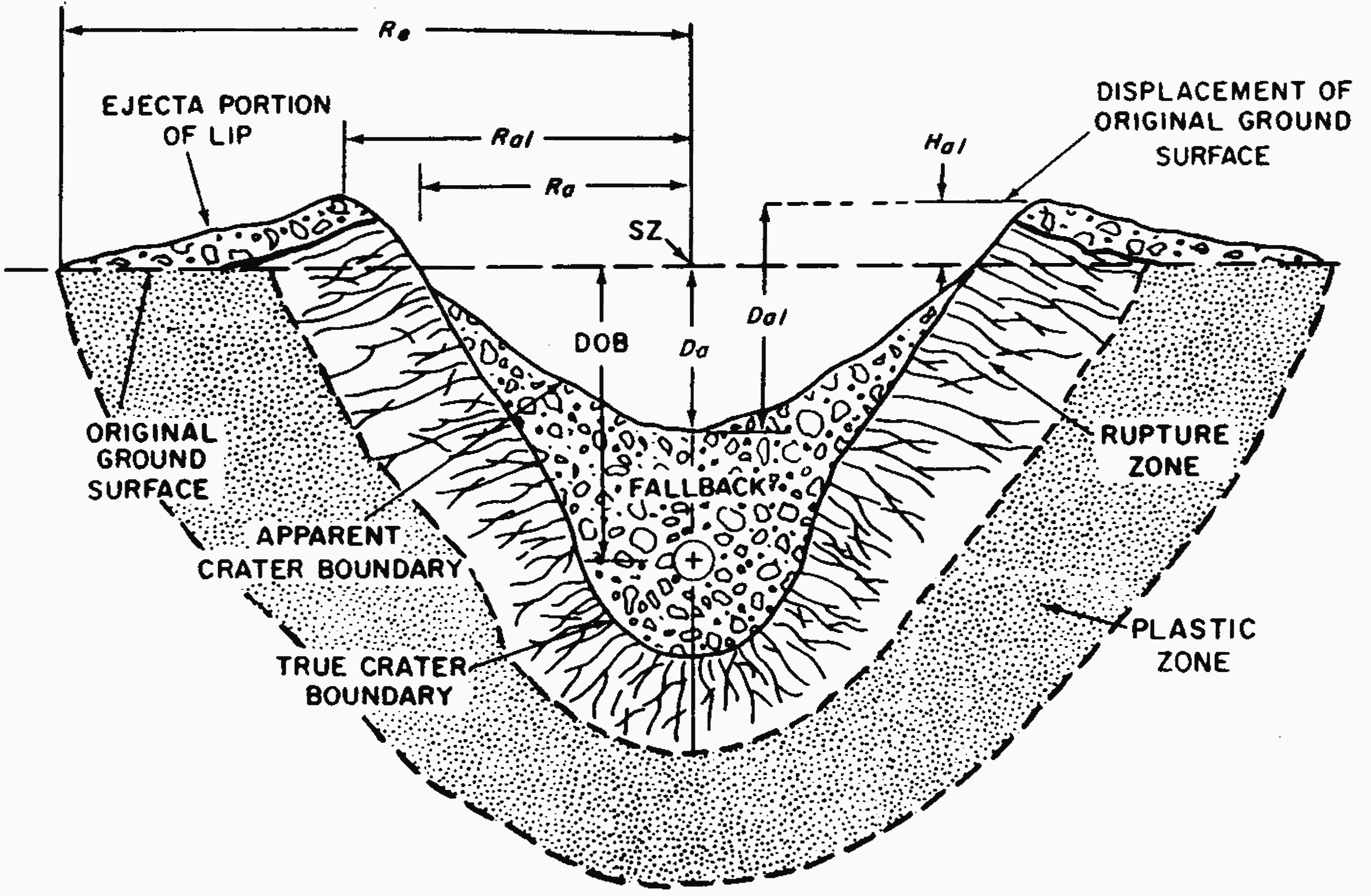
6.71 Values of other crater parameters indicated in Fig. 6.70 can be estimated with respect to the apparent crater radius and the apparent crater depth by the following relations. The radius to the crater lip crest, $R_{al}$, is
\[ R_{al} \approx 1.25 R_a. \]The height of the lip crest, $D_{al}$, is
\[ D_{al} \approx 1.25 D_a. \]The height of the apparent lip above the original ground surface, $H_{al}$, is
\[ H_{al} \approx 0.25 D_a. \] Thus, if $R_a$ and $D_a$ are known, the quantities given above (and others defined in § 6.74 et seq.) can be estimated.6.72 Crater dimensions depend upon the depth of burst (or burial), the explosion energy yield, and the characteristics of the soil. The apparent crater radius and depth, as functions of the depth of burst, are given in Figs. 6.72a and b for a 1-kiloton explosion in four media. For bursts just above the surface, the heights of burst are treated as negative depths of burst. Because of the rapid change in crater dimensions as the depth of bursts passes through zero, the values for a contact surface burst are shown explicitly on the figures. The best empirical fit to crater data indicates that, for a given scaled depth of burst, i.e., actual depth divided by $W^{0.3}$, both the radius and depth vary approximately as $W^{0.3}$, where $W$ is the weapon yield. The procedure for calculating the dimensions of the apparent crater for any specified depth of burst and yield by means of these scaling rules is illustrated in the example facing Fig. 6.72a. The maxima in the curves indicate the so-called optimum depths of burst. It is evident that a change in the moisture content of a soil or rock medium can have a significant influence on the size of a crater; a higher moisture content increases the crater size by increasing the plasticity of a soil medium, weakening a rock medium, and providing a better coupling of the explosive energy to both soil and rock media.
CRATER EJECTA
6.73 Crater ejecta consist of soil or rock debris that is thrown beyond the boundaries of the apparent crater. Together with the fallback, which lies between the true and apparent crater boundaries, ejecta comprise all material completely disassociated from the parent medium by the explosion. The ejecta field is divided into two zones: (1) the crater lip including the continuous ejecta surrounding the apparent crater (Fig. 6.70), and (2) the discontinuous ejecta, comprising the discrete missiles that fall beyond the limit of the continuous ejecta.
6.74 The amount and extent of the continuous ejecta in the crater lip are determined primarily by the explosion yield and the location of the burst point, although the characteristics of the medium have some effect. The radial limit of the continuous ejecta, which is the cloud which is blown away). For an outer edge of the lip, will usually vary from two to three times the apparent crater radius. In most cases, a satisfactory approximation to the radius of the continuous ejecta, $R_e$ (Fig. 6.70), is
\[ R_e \approx 2.15 R_a. \]6.75 The depth of the ejecta decreases rapidly in an exponential manner as the distance from surface zero increases. In general, about 80 to 90 percent of the entire ejecta volume is deposited within the area of the continuous ejecta. Analysis of data for craters formed by nuclear bursts in soil indicates that ejecta mass represents approximately 55 percent of the apparent crater mass (the remainder being found in fallback, compaction, and the dust cloud which is blown away). For an explosion of given yield, the ejecta mass increases significantly with the depth of burst until the optimum depth is reached. Ejecta thickness can be estimated for soil in terms .of the apparent radius and diameter; thus:
where $t_e$ is the ejecta thickness and $R$ is the distance from surface zero to the point of interest. In equation (6.75.1), it is assumed that the ejecta mass density is approximately equal to the original in-situ density of the medium, which could be considered valid for a soil medium. However, the bulking inherent in disturbed rock media would result in ejecta thicknesses about 30 percent greater than predicted by equation (6.75.1).
GEOLOGIC FACTORS
6.76 In addition to the nature and water content of the soil, certain other geologic factors may influence crater size and shape. Terrain slopes of about 5° or more will affect the geometry of a crater formed by either surface or buried explosions, with the influence of the slope being more evident as burst depth increases. The surface slope will cause much of the debris ejected by the explosion to fall on the downslope side of the crater, often resulting in rockslides below the crater area. In addition, the upslope rupture zone may collapse into the crater, resulting in an asymmetric crater shape.
6.77 In rock, the dip of bedding planes will influence energy propagation, causing the maximum crater depth to be offset in the down-dip direction. Little overall effect is noted in regard to crater radius, but differences in ejecta angles cause the maximum lip height and ejecta radius to occur in the down dip direction.
6.78 A subsurface groundwater table in a soil medium will begin to influence the size and shape of the crater when the water table is above the detonation point. Its effect is to flatten and widen the crater. The influence of a bedrock layer below a soil medium is similar to that of a water table, although somewhat less pronounced. For explosions at or near the surface, the bedrock layer has little effect on the crater radius, but may decrease the final depth considerably.
6.79 For relatively low-yield explosions at or very near the surface, the bedding or jointing planes in rock can alter significantly the shape of the crater and the direction of the ejection. The crater shape will tend to follow the direction of the predominant joints; the crater radius will increase in the direction parallel to the joints and decrease normal to the joints.
AIR BLAST PRESSURE
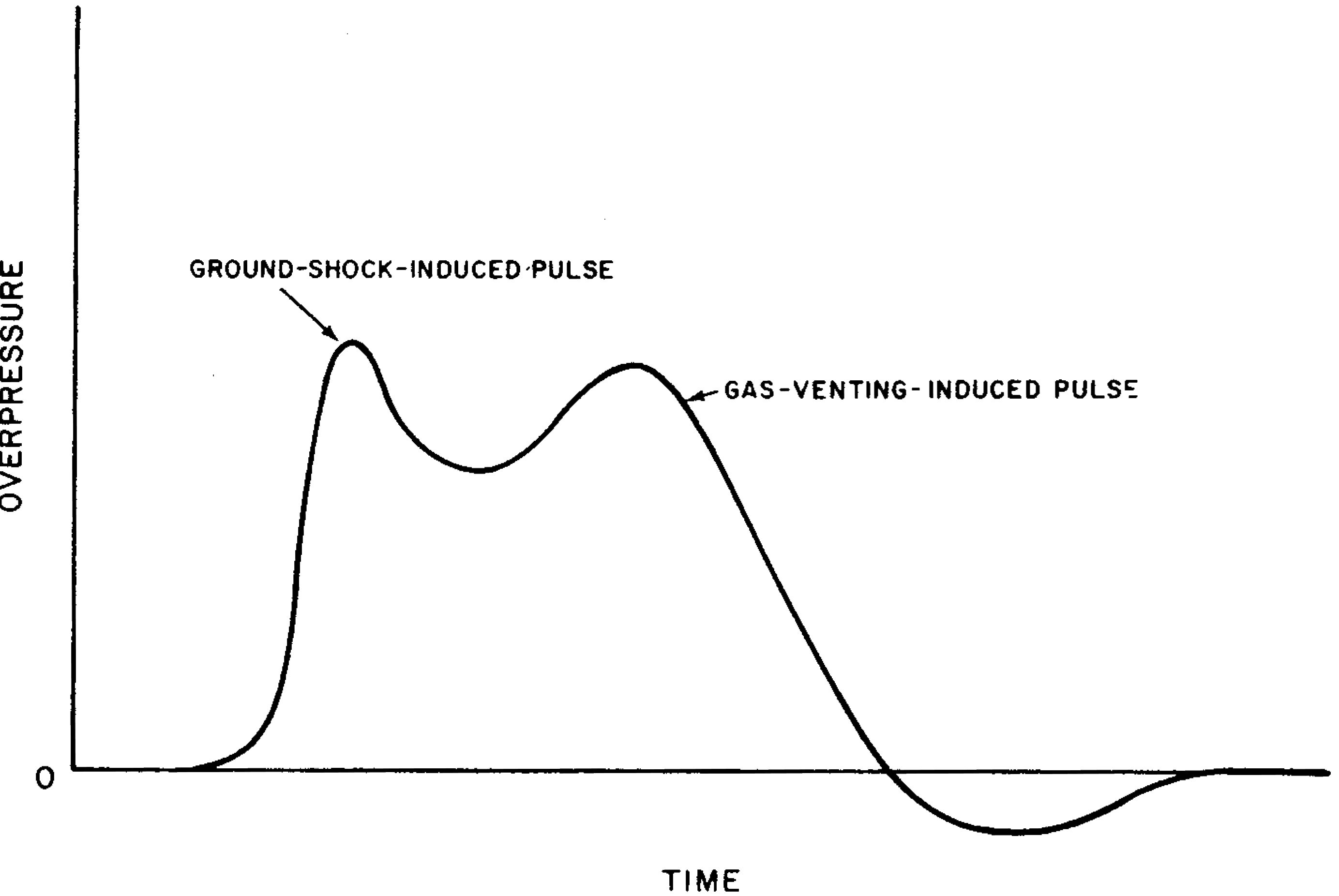
6.80 Several different mechanisms may operate to transfer part of the energy released in an underground explosion into the air and thereby produce air blast. For explosions at moderate depths, such that the fireball does not break through the surface, the predominant mechanisms may be described as follows. A shock wave propagated through the ground arrives at the surface and imparts an upward velocity to the air (air particles) at the air-ground interface, thus initiating an air pulse. At the same time, there may be spalling and upward motion of the surface layers, as explained in § 2.91. Meanwhile, the underground explosion gases expand, pushing the earth upward so that the spall merges into a dome at surface zero. The piston-like action of the spall and the rising dome increase the duration of the initial air pulse. The air blast sustained in this manner appears on pressure-time records as a single pulse, termed the air-transmitted, ground-shock-induced pulse. Somewhat later, the explosion gases puncture the dome and escape, creating a second air pulse called the gas-venting-induced pulse (Fig, 6.80).
6.81 With increasing depth of burst, the relative contribution of gas venting decreases and the time between the two pulses increases. Although the mechanisms that generate the air pulses change with depth in a complex manner, a procedure has been developed for predicting peak overpressures in the air near the surface as a function of distance from surface zero over a reasonable range of burial depths; the results are shown in Fig. 6.81. The value of x may be obtained from the following relations:
\[ \overline{x} = \lambda_x e^{\rho \lambda_d / 126}, \lambda_x = x/W^{1/3} \text{ and } \lambda_d = d/W^{1/3}, \]where $x$ = ground distance in feet, $d$ = depth of the explosion in feet, $W$ = explosion yield in kilotons, and $p$ = specific gravity of the ground medium. The curve in Fig. 6.81 may be used with the relations given above for scaled depths of burst, $\lambda_d$, less than 252 feet/KT1/3. Typical values of specific gravities are 1.6 for alluvium, 1.9 for tuff, and 2.7 for granite.

GROUND MOTION
6.82 Earth shock motion at or near the surface accompanying a shallow or moderately deep underground burst may be regarded as consisting of systemic and random effects. The systemic effects are those associated with air blast and the shock wave transmitted directly through the ground from the detonation (§ 6.12 et seq.). Random effects include high-frequency shock waves in the ground, surface wave effects, reflections, refractions, etc. They depend on such factors as the explosion yield, distance from surface zero, depth of the observation point, and, in particular, the local geologic conditions. The following discussion will be concerned mainly with the systemic effects.
6.83 In the superseismic situation, the downward acceleration of the ground due to the air blast is large compared with the subsequent upward acceleration caused by the direct ground shock. The record of ground acceleration (or velocity) versus time obtained on a gauge mounted near the surface is similar in shape to the air overpressure time pulse, at least in the early stages. When the direct ground shock wave outruns the air blast, there is a slower increase in the acceleration and the direction may be upward rather than downward. The acceleration-time pulse may then last for a longer time than the duration of the positive air overpressure pulse. The overall motion record is characterized by a considerable degree of oscillation. When precursors (§§ 3.49, 3.79) are present, the records may exhibit components of higher frequency and a more random type of oscillation.
6.84 By using data obtained during various nuclear tests, expressions have been derived from which peak ground acceleration, velocity, and displacement (transient and permanent), both at the surface and down to moderate depths, in the superseismic condition can be estimated from the peak air overpressure as evaluated in § 6.81. No simple method is presently available for calculating the effects of outrunning ground motion. As far as the effects of the direct shock wave are concerned, the expected results are inferred mainly from data obtained at deep underground tests in which the air blast is negligible. The response of structures to seismic (or elastic) waves generated at a distance from the burst point by the ground shock wave is considered in § 6.90 et seq.
TECHNICAL ASPECTS OF DEEP UNDERGROUND BURSTS
CAVITY AND CHIMNEY DIMENSIONS
6.85 The dimensions of the gas cavity and the chimney formed in a deep underground explosion depend on the energy yield, on the nature of the medium in which the explosion occurs, on that in which the chimney develops, and to some extent on the depth of burial. Because of the variability of the conditions, it is not possible to state a relationship among the factors involved. The purpose of the following treatment is only to give some rough indications of cavity and chimney dimensions and it should not be taken as providing definitive information.
6.86 As a rough approximation, the volume of the cavity in a given medium and fixed depth of burial may be taken to be proportional to the explosion energy. Hence, if the cavity is assumed to be spherical, its radius should be proportional to $W^{1/3}$, where $W$ is the energy yield. Measurements indicate that this relationship is very roughly true, so that $R_c/W^{1/3}$, where $R_e$ is the cavity radius, is approximately constant for a given medium and burst depth. For moderately deep, contained explosions the effect of burst depth is small and the following values have been found for $R_c/W^{1/3}$ in two types of media:
\[ \begin{aligned} &\text{Dense silicate rocks (e.g., granite)} \dots \text{35 feet/KT}^{1/3}\\ &\text{Dense carbonate rocks (e.g., dolomite, limestone)} \dots \text{25 feet/KT}^{1/3}\\ \end{aligned} \]These expressions are applicable approximately for burst depths below about 2,000 feet.
6.87 At greater burst depths, the pressure of the overburden, which must be overcome in forming the gas cavity, has some effect on the cavity radius. On the basis of adiabatic compression of the overburden material, the cavity radius would be expected to be inversely proportional to $(\rho h)^{0.25}$, where $\rho$ is the density and $h$ is the height of the overburden. Limited observations, however, indicate that the exponent may differ significantly from 0.25. It appears, therefore, that a number of factors, which are not well understood, affect the relationship between the cavity radius and the overburden pressure at depths exceeding 2,000 feet.
6.88 If the roof of the gas cavity collapses upon cooling, as it generally (but not always) does, the dimensions of the chimney are highly dependent upon the characteristics of the medium in which it is formed. As a general rule, the radius of the chimney is from 10 to 20 percent greater than that of the cavity. Furthermore, the height of the chimney may be from about four to six times the cavity radius. The higher factor appears to apply to completely bulked granite and the lower to dolomite, shale, and incompletely bulked granite.
6.89 From the foregoing rough data, it appears that for an underground explosion in which the top of the chimney does not reach the earth’s surface the scaled depth of burial, i.e., $d/W^{1/3}$, must be greater than about 300 feet/KT1/3. If the top of the chimney is fairly close to the surface, however, some of the radioactive gases formed in the nuclear detonation could seep through the ground into the atmosphere. In conducting underground tests, the escape of these gases must be prevented. The scaled depth of burial is consequently not less than 400 feet/KT1/3. For explosions of low yield, when the actual depth of burial would be relatively small, and in media with a substantial water content, the scaled depths of burial are increased even more in order to achieve containment of radioactive gases.
STRUCTURAL RESPONSE TO GROUND MOTION
6.90 A semiempirical method for studying (and predicting) the response of structures to ground motion caused by the seismic wave from an underground explosion makes use of the “response spectrum.” A linear oscillator with a single mode of vibration, which may be thought of as a simple idealized structure, is considered. It is assumed to be subjected to the entire history of the ground motion as actually recorded on a seismic instrument at a given location. By utilizing the laws of mechanics, the peak response of the idealized structure to the ground motion can then be calculated. For an elastic oscillator, this response depends only on the natural vibration period (or frequency) of the oscillator and the damping ratio. A particular damping ratio is selected, e.g., 0.05, and the peak structural response is calculated for one specified vibration period by means of the procedure just described. The calculation is repeated for a range of vibration periods, generally from about 0.05 to 10 seconds. The results are plotted on a special logarithmic paper to give the response spectrum corresponding to the specified damping ratio and observed ground motion. Because the peak acceleration, velocity, and displacement are related mathematically, a single curve gives the variation of these quantities with the vibration period of the idealized structure.
6.91 From the response spectrum at a given location it is possible to deter mine the relative amounts of ground motion energy, from an explosion of specified yield, that would cause vibration of structures with different natural vibration periods. The general conclusions stated in § 6.37 et seq., concerning the response of structures to the seismic motion accompanying underground nuclear explosions, were reached from a study of response spectra derived from many ground motion records obtained at various locations in the vicinity of the Nevada Test Site.
6.92 The response spectrum is calculated from the actual ground motion, which depends primarily on the yield of the explosion, the depth of burst, and the distance from the burst point. In addition, however, the nature of the medium through which the seismic wave is propagated and of the ground upon which the structure stands have an important influence. Because of the large amount of information accumulated in underground explosions at the Nevada Test Site, reasonably good predictions can be made of the ground motions and hence of the response spectra in the general area of the site. For underground explosions in other areas, the results from Nevada are used as the basis for preliminary calculations of response spectra. Modifications are then made for differences in geology.
6.93 If the characteristics of a structure are known, an engineer experienced in such matters can predict from the response spectrum whether the structure will be damaged or not by a specified underground nuclear explosion at a given distance. In making these predictions, it must be recalled that a response spectrum applies to a range of linear, elastic oscillators, each with a single vibration period and an assumed damping ratio. Such and oscillator may be identified approximately with a simple, idealized structure having the same respective vibration period and damping ratio. In real-life situations, however, buildings do not behave as ideal structures with a single vibration period and, moreover, the damping ratios vary, although 0.05 is a reasonable average value. Consequently, in making damage estimates, allowances must be made for several variables, including structural details, different vibration periods, and the type, age, and condition of the structure.
LOADING ON BURIED STRUCTURES
GENERAL CONSIDERATIONS
6.94 Of the ground motions resulting from a nuclear burst at or near the surface (§ 6.12 et. seq.) two types (air slap and outrunning) are traceable to the pressure of the airblast wave on the ground surface. Only in the immediate neighborhood of the crater will directly coupled ground motion be a significant damage mechanism. For example, a 1 kiloton explosion on the surface leaves a crater approximately 49 to 82 feet radius (Fig. 6.72a). Yet the free-field peak air blast overpressure, i.e., the overpressure in the absence of structures, at a distance of two crater radii from surface zero is several thousand pounds per square inch (Fig. 3.73a) and remains above 100 pounds per square inch up to a distance of five or six crater radii. Outrunning ground motion generally occurs so far from surface zero that it is relatively small. Therefore, unless a structure is extremely deeply buried, i.e., its distance from the surface is similar to its distance from surface zero, the major threat to it is most likely to arise from airslap. For shallow-buried structures, the air blast overpressure may consequently be taken as the effective load. For deeply-buried structures, attenuation of the shock must be considered.
6.95 For the purposes of making loading estimates for buried structures, the medium may be described as soil or rock. In soil, the structure must resist most of the load, whereas in rock, the medium itself may carry a large part of the load.
ARCHING EFFECT
6.96 If the deformability of a buried structure is the same as that of the surrounding displaced soil, the loads produced on the structure by the air blast from a nuclear detonation will be determined by the free-field pressures induced in the soil by the blast wave. If the deformability of the structure is greater or less than that of the soil, the pressures on the structure will be less or greater, respectively, than those in the soil.
6.97 Results of tests have indicated that there is no significant buildup of pressure due to reflection at the interface between the soil and a buried structure. It may be assumed, therefore, that structures are at least as deformable as soils and that the free-field pressure, regardless of its direction, can be taken as an upper limit of the pressure acting on the structure. If the structure is much more deformable than the surrounding soil, the pressure on the buried structure will be considerably lower than the free-field pressure at the given depth. In this case, as the free-field pressure is exerted initially, the structure deflects away from the soil and a situation is created in which the “arching effect” within the soil serves to transmit part of the blast-induced pressure around the structure rather than through it. Arch ing, properly speaking, belongs to the loading process, but it may also be treated as a factor that enhances the resistance of the structure.
6.98 In soil, the load carrying ability of the medium is a form of arching. The degree of arching is determined by (1) the structural shape and (2) the ratio of the roof span to depth of burial. Shells, such as arches and domes, develop significant arching resistance in soils; rectangular structures generally do so to a lesser extent.
6.99 The weight of the overburden on a buried structure represents a force that must be overcome. Hence, the structural strength remaining to oppose the shock decreases as the depth of burial is increased. This effect of increasing overburden on a structure is countered to some extent by the opposite effect of arching.
LOADING ON BURIED RECTANGULAR STRUCTURES
6.100 The treatment of the air blast-induced loads on shallow-buried rectangular (or box-type) structures resulting from surface or shallow underground bursts is similar to the treatment of loads on buried structures from air bursts. Thus, the procedures described in§ 5.156 et seq. are applicable, except that the overpressure at the surface should be obtained by the method described in § 6.81. For a column-supported slab, capitals between the columns and the slab may greatly increase the structural resistance.
LOADING ON BURIED ARCHES AND DOMES
6.101 On buried arches and domes the actual loading is considerably more complex because of the constantly changing attitude of the surface of the structure with respect to a horizontal plane and also because, at very shallow depths, the initial nonuniformity of load cannot be neglected. As a blast wave passes over a buried arch or dome, the side closest to the explosion is loaded earlier than the farther side and, consequently, an unsymmetrical flexural (or bending) mode of response is excited. Furthermore, after the structure is completely engulfed by the blast wave, the radial (inwardly directed) loading will be very nearly symmetrical, although not uniform. The pressure at the crown, corresponding to the free-field vertical pressure close to the ground surface, is then the maximum. Beyond the crown, the radial pressure decreases in intensity to a minimum at the springing line where, if the arch or dome has a 180° central angle, the pressure will correspond to the free-field lateral (sideways) pressure at the depth of the footings. This symmetrical nonuniform loading tends to excite a symmetrical flexural mode of response. In addition to these two flexural modes, the structures will also respond in a direct compression mode.
6.102 For the flexural modes to be significant, deformations corresponding to these modes must be possible. For such deformations to occur, the passive resistance of the surrounding soil must be overcome and a wedge of the soil must be displaced by the deforming structure. Thus, the passive resistance of the soil will tend to limit these deformations and prevent the flexural modes from being significant. Although the flexural modes may be important with shallow buried structures, they decrease in importance very rapidly with depth since the passive resistance of the soil increases quite rapidly at the same time.
6.103 In the foregoing discussion it is assumed that the footings do not move with respect to the soil adjacent to them. If the footings do penetrate into the underlying material, the radial pressures on the arch or dome may be reduced slightly.
DAMAGE FROM GROUND SHOCK
UNDERGROUND STRUCTURES
6.104 The damage to an underground structure itself, as distinct from the effects of ground shock on its contents (§ 6.112), can be readily defined in terms of inelastic deformation or collapse. For fully buried arches and domes, severe damage corresponds to collapse either by elastic or, more frequently, inelastic buckling. If very near the ground surface, the deformations may be primarily flexural. Light damage has little or no meaning unless it refers to partial impairment of operational capability of personnel and equipment. Moderate structural damage for concrete structures can be defined as deformation accompanied by significant spalling. Such deformation would correspond to stress levels in the concrete slightly above the yield point, i.e., a ductility factor of about 1.3. This presumes that failure is by inelastic deformation rather than by elastic buckling, as would be the case in a properly designed blast-resistant structure. If failure is by elastic buckling, moderate damage cannot be realized.
6.105 For steel arches and domes, moderate structural damage can also be defined in terms of a reduced ductility factor, although the nature of such damage for steel structures is not as clearly evident as in the spalling of concrete. For underground, blast-resistant, box-type structures, the several degrees of damage to arches and domes are also applicable, but the mechanism of deformation may be different. In a box structure, primary response may be in flexure of the walls, roof, or base slabs or in direct stress or buckling of the walls or columns. However, severe damage is still characterized by excessive deformation or collapse through any of these mechanisms; moderate damage corresponds to deformations of any of the elements associated with spalling of concrete and small permanent deflections; and light damage is virtually meaningless except in terms of shock effects on personnel and equipment.
6.106 For very low yield weapons, it is difficult to produce significant damage to a buried structure unless it is within the rupture zone around the crater (Fig. 6.70). With the exception of a number of special structural types, e.g., pipelines and small highly resistant reinforced-concrete fortifications, soil pressures produced by air blast pressures on the ground surface constitute the primary source of damage to buried structures.
6.107 It is expected that underground structures whose span closely matches one-half the wavelength of the shock will “roll with the blow.” This expectation has been borne out by actual experience. The movement of the structure is intimately connected with the movement of the soil as the shock wave passes. In other words, if the particle acceleration in the soil has certain peak horizontal and vertical components, then the small underground structure may be expected to have almost the same peak acceleration components.
6.108 Shock damage to underground structures is most frequently calculated with computer codes. Graphs and tables suitable for hand calculations have been developed, but such calculations are time consuming, and the results are approximations at best. There is evidence that the degrees of damage from shallow (and moderately shallow) explosions can be related to the apparent crater radius. Some examples of this relationship are given in Table 6.108 for moderately deep underground structures, defined as structures for which the ratio of the depth of cover at the crown to the span is somewhat greater than unity. Crater radii, and hence the dam age distances, will vary with soil type (§ 6.72). Deeply buried structures, with a ratio of depth of cover to span much greater than unity, would suffer less damage.
| Structural Type | Damage Type | Distance from Surface Zero | Nature of Damage |
|---|---|---|---|
| Relatively small, heavy, well-designed, underground structures. | Severe | 1¼ apparent crater radii | Collapse |
| Light | 2½ apparent crater radii | Slight cracking, severance of brittle external connections | |
| Relatively long, flexible structures, e.g., buried pipelines, tanks, etc. | Severe | 1½ apparent crater radii | Deformation and rupture |
| Moderate | 2 apparent crater radii | Slight deformation and rupture | |
| Light | 2 to 3 apparent crater radii | Failure of connections |
6.109 Although tunnels and subways would be destroyed within the crater region and would suffer damage outside this area, these structures, especially when bored through solid rock and lined to minimize spalling, are very resistant to ground shock. The rock, being an elastic medium, will transmit the pressure (compression) wave very well, and when this wave strikes the wall of the tunnel, a tension (negative pressure) wave is reflected from the rock-air interface.5 Even in a soil medium, tunnels and subways could survive; flexible structures would resist damage by taking advantage of the tremendous passive earth pressure. However, construction in soil should be above the water table, if possible.
6.110 Under certain circumstances, failure of the rock at the tunnel wall will result in spalling when the reflected tensile stress exceeds the tensile strength of the rock. The thickness of spalling is dependent upon the magnitude, duration, and shape of the pressure wave, upon the size and shape of the tunnel, and upon the physical properties of the rock.
6.111 A structure may extend above the grade level but be protected by earth piled or mounded around it (Fig. 6.111). The idealized surface is the surface of constant slope which is equivalent to the actual (curved) surface. If the slope of the idealized surface is less than 14°, the structure may be treated as buried, and the foregoing discussion of buried arches and domes is applicable. If the slope is more than 14°, or if the structure is located well beyond the plastic zone, the overall damage is determined by air blast, and is in accordance with the discussion in Chapters IV and V.

VULNERABILITY OF EQUIPMENT
6.112 Although a structure may suffer little or no damage from ground motion, its contents, e.g., machinery or other equipment, may be rendered inoperative by the shock. Such equipment may be made less vulnerable by suitable shock mounting. Shock mounts (or shock isolators) are commonly made of an elastic material like rubber or they may consist of springs. The material absorbs much of the energy delivered very rapidly by the shock and releases it more slowly, thereby protecting the mounted equipment.
6.113 By shaking, vibrating, or dropping pieces of equipment, engineers can often estimate the vulnerability of that equipment to all kinds of motion. The results are commonly expressed as the natural vibration frequency at which the equipment is most vulnerable and the maximum acceleration tolerable at that frequency for 50 percent probability of severe damage. Some examples of the values of these parameters for four classes of equipment, without and with shock mounting, are quoted in Table 6.113. It is seen that the shock mounting serves to decrease the most sensitive natural frequency, i.e., increase the period, and to increase the acceleration for 50 percent probability of severe damage at that frequency.
| Class | Item | Shock Mounted | Typical Value of Natural frequency (cps) | Typical Value of Vulnerability acceleration (g) |
|---|---|---|---|---|
| A | Heavy machinery-motors, generators, transformers, etc. (>4000 lb). | No | 10 | 20 |
| Yes | 3 | 40 | ||
| B | Medium and light machinery-pumps, condensers, air conditioning, fans, small motors (<1000 lb). | No | 20 | 40 |
| Yes | 5 | 80 | ||
| C | Communication equipment, relays, rotating magnetic drum units of electronic equipment, etc. | No | 25 | 7 |
| Yes | 6 | 60 | ||
| D | Storage batteries, piping and duct work. | No | 20 | 70 |
| Yes | 5 | 150 |
6.114 Whether or not a specified piece of equipment is likely to be damaged by a particular ground motion can be estimated from the data in Table 6.113 in conjunction with the response spectrum (§ 6.90) for that ground motion. If the peak acceleration on the response spectrum corresponding to the equipment frequency is less than the vulnerability acceleration, then the equipment will probably be undamaged by the particular ground motion. On the other hand, if the response spectrum indicates that the equipment may be damaged, shock mounting should be added or improved.
TECHNICAL ASPECTS OF UNDERWATER BURSTS
SHOCK WAVE PROPERTIES
6.115 By combining a theoretical treatment with measurements made in connection with detonations of high explosive charges under water, some characteristic properties of the under water shock wave from a nuclear explosion have been calculated. The peak pressure of the shock wave in water for various energy yields is shown in Fig. 6.115 as a function of slant range, $R$, for pressures less than 3,000 pounds per square inch and (in the top right corner) as a function of the scaled slant range, $R/W^{1/3}$, for higher pressures. The data refer to “isovelocity” water, i.e., water in which there are no reflections or refractions.
6.116 The decrease of the water pressure with time can be obtained from Figs. 6.116a and b. The former gives the time constant, 0, in terms of the slant range for various yields, and the latter shows the variation of $p(t)/p$, where $p(t)$ is the pressure at time $t$ after the arrival of the shock front at the observation point and $p$ is the peak pressure at that point, with the reduced time $t/0$. The time constant is the time at which the shock pressure has decayed to $1/e$, i.e., about 37 percent, of its peak value. (The use of a time constant defined in this manner must not be taken to imply that the pressure decreases exponentially; it does not do so except at early times.) The longer the time constant, the more slowly does the water shock pressure decay; it is apparent, therefore, from Fig. 6.116a that the duration of the shock wave increases with the energy yield and the distance from the explosion point. The data in Figs. 6.116a and b may be used to construct a curve showing the decrease with time of the pressure at a specified slant range from an underwater explosion of given yield. The area under the curve gives the pressure impulse of the water shock wave, analogous to the air overpressure impulse defined in § 3.59.
6.117 In shallow water and in certain circumstances in deep water, the primary underwater shock pulse will be modified by surface and bottom effects (§ 6.41 et seq.). Water is much less compressible than air, and positive reflection phenomena (§ 6.49) are less well understood than reflections of air shocks from the ground and other surfaces. Bottom reflections in water are frequently more nearly acoustic than air blast reflections. Consequently, under appropriate conditions, the influence of the bottom can be treated ideally by replacing the bottom surface with an image explosion of the same yield as the actual explosion located a distance below the bottom equal to the distance of the actual explosion above it.
6.118 In practice, the character of the bottom, e.g., mud, loose or packed sand, or hard rock, has a marked effect on the magnitude of the reflected pressure. The distances traveled by the primary shock and reflected waves to the target also influence the pressures. When the explosion and the target are both near the bottom, the reflected pressure received at the target may be greater than, equal to, or less than the primary pressure. When the burst point and the target are both remote from the bottom, the reflected pressure is generally much smaller because of the greater travel distance. In each case, of course, the negative pressure reflected from the air-water interface must not be overlooked. The times of arrival of the reflected pressures, after the primary shock, may be estimated from the respective travel distances by assuming that the pulses travel with the speed of sound in the water.
SURFACE WAVES
6.119 When observed at a point remote from surface zero, the idealized surface displacement associated with the train of waves referred to in § 6.54 is shown in Fig. 6.119. In deep water, the wave intensity is represented by the peak-to-peak height $H$ of the wave envelope. The manner in which this height diminishes with distance (or radius) $R$ from surface zero can be expressed to an accuracy of about 35 percent by the relationship
with both $H$ and $R$ in feet, and the yield $W$ in kilotons TNT equivalent. This expression holds provided the depth, $d_w$, feet, of the water in which the surface waves are produced is in the range $850 W^{0.25} \geq d_w \geq 256 W^{0.25}$, where the lower limit is the maximum diameter of the gas bubble (§ 2.86). The relation is valid for any depth of burst within the water. Other parameters characterizing surface waves are the length $L$ and period $T$ of the peak wave. Extrapolation of deep water chemical explosions indicate these quantities are given approximately by
\[ \begin{aligned} L \approx \; &1010 \; W^{0.288} \text{ feet}\\ T \approx \; &14.1 \; W^{0.144} \text{ seconds} \end{aligned} \]where $W$ is in kilotons.

6.120 The length is a critical factor in determining the changes taking place in a wave train running into shoal water (§ 6.59). If water depth becomes less than approximately $L/3$, successive waves in the train bunch up while wave speed increases. The period $T$ remains the same. Of equal or greater importance is the fact that, after an initial small decrease, the height $H$ increases as the water through which the wave is running becomes more shallow. The increase in height of a wave relative to its length (steepening) continues as the wave shoals until it becomes unstable and breaks, unless the bottom slope is so shallow that bottom friction dissipates the wave before it breaks.
6.121 A burst in shallow water such as Bikini BAKER, delivers less energy to the water than a burst of the same yield in deep water; consequently the constant of proportionality in equation (6.119.1) becomes less as water depth decreases. An approximate relationship between wave height H and distance R from surface zero for a shallow burst $(d_w \geq l00 W^{0.25})$ is
\[ H \approx \; 150 \; d_w\frac{W^{0.25}}{R} \]with $H$ and $R$ in feet.
DAMAGE TO HYDRAULIC STRUCTURES
6.122 As is the case with air blast, it is to be expected that the damage to an underwater structure resulting from water shock will depend upon the dimensions of the structure and certain characteristic times. The particular times which appear to be significant are, on the one hand, the time constant of the shock wave (§ 6.116) and, on the other hand, the natural (or elastic) response time and the diffraction time of the structure, i.e., the time required for the shock wave to be propagated distances of the order of magnitude of the dimensions of the structure. In the event that the underwater structure is near the surface, the cutoff time (§ 6.43) would be significant in certain cases.
6.123 If the time constant of the pressure wave and the cutoff time are large compared to the times which are characteristic of the structure, that is to say, if the water shock wave is one of relatively long duration, the effect of the shock is similar to that of a steady (or static) pressure applied suddenly. In these circumstances, the peak pressure is the appropriate criterion of damage. Such would be the case for small, rigid underwater structures, since they can be expected to have short characteristic times.
6.124 For large, rigid underwater structures, where the duration of the shock wave is short in comparison with the characteristic times of the structure, the impulse of the shock wave will be significant in determining the damage. It should be remembered, in this connection, that the magnitude of the impulse and damage will be greatly decreased if the negative reflected wave from the air-water surface reaches the target and causes a cutoff soon after the arrival of the primary shock wave.
6.125 If the large underwater structure can accept a substantial amount of permanent (plastic) deformation as a result of impact with the shock front, it appears that the damage depends essentially on the energy of the shock wave. If the structure is near the surface, the cutoff effect will decrease the amount of shock energy available for causing damage.
BIBLIOGRAPHY
- , “Refraction of Underwater Explosion Shock Waves: Pressure Histories Measured at Caustics in a Flooded Quarry,” U.S. Naval Ordnance Laboratory, April 1967, NOLTR–67–9.
- , “Project SEDAN, Mass Distribution and Throwout Studies,” The Boeing Company, Seattle, Washington, August 1963, PNE–217E.
- , “Nuclear Cratering Experience at the Pacific Proving Grounds,” University of California, Lawrence Radiation Laboratory, November 1964, UCRL–12172.
- , “Underwater Explosions,” Dover Publications, Inc., 1965. (Reprint of 1948 edition, Princeton University Press.)
- , “MINE SHAFT Series, Events MINE UNDER and MINE ORE, Subtask, N121, Crater Investigations,” U.S. Army Engineer Waterways Experiment Station, March 1970, Technical Report N–70–8.
- , “Seismic Effects of the MILROW and CANNIKIN Nuclear Explosions,” Bull. Seismol. Soc. America, 62, 1411 (1972).
- , “MIDDLE COURSE I Cratering Series,” U.S. Army Engineer Nuclear Cratering Group, June 1971, Technical Report 35. FRANDSEN, A. D., “Project CABRIOLET, Engineering Properties Investigations of the CABRIOLET Crater,” U.S. Army Engineer Nuclear Cratering Group, March 1970, PNE–957.
- , “Public Safety and Underground Nuclear Detonations,” U.S. Atomic Energy Commission, June 1971, TID–25708.
- , “Nuclear Explosions and Distant Earthquakes: A Search for Correlations,” Science, 169, 176 (1970).
- , “Hydra Program: Theoretical Study of Bubble Behavior in Underwater Explosions,” U.S. Naval Radiological Defense Laboratory, April 1964, USNRDL–TR–747.
- , “Mechanisms in the Generation of Airblast by Underwater Explosions,” U.S. Naval Ordnance Laboratory, September 1966, Bolt, Beranek and Newman Report No. 1434, NOLTR–66–88.
- , “Preliminary Design Methods for Underground Protective Structures,” University of Illinois, June 1962, AFSWC–TDR–62–6.
- , “Notes on Shock Isolation Concepts,” Vibration and Civil Engineering Proceedings of Symposium of British National Section International Association for Earthquake Engineering, p. 71, Butterworths, Lon don, 1966.
- , “Underwater Explosion Tests of Two Steam Producing Explosives, I. Small Charge Tests,” U.S. Naval Ordnance Laboratory, May 1966, NOLTR–66–79.
- *“Proceedings of the Second Plowshare Symposium,” Part I, Phenomenology of Underground Nuclear Explosions,” University of California, Lawrence Radiation Laboratory, Livermore, May 1959, UCRL–5677.
- *“Proceedings of the Third Plowshare Symposium, Engineering with Nuclear Explosives,” April 1964, University of California, Lawrence Radiation Laboratory, Livermore, TID–7695.
- *“Proceedings of the Symposium on Engineering with Nuclear Explosives,” Las Vegas, Nevada, January 1970, American Nuclear Society and U.S. Atomic Energy Commission, CONF–700101, Vols, I and 2.
- , “Nuclear Explosion Seismology,” AEC Critical Review Series, U.S. Atomic Energy Commission, September 1971, TID–25572.
- , “FERRIS WHEEL Series, FLAT TOP Event, Crater Measurements,” U.S. Army Engineer Waterways Experiment Station, August 1966, POR–3008.
- , “Hydrodynamic Concepts, Selected Topics for Underwater Nuclear Explosions,” U.S. Naval Ordnance Laboratory, September 1966, NOLTR–65–52.
- Special Papers on Underground Nuclear Explosions at the Nevada Test Site, Bull. Seismol. Soc. America, 59, 2167 et seq. (1969).
- Special Papers on the CANNIKIN Nuclear Explosion, Bull. Seismol. Soc. America, 62, I 365 et seq. (1972).
- , “Handbook of Explosion-Generated Water Waves, Vol. I—State of the Art,” Tetra Tech, Inc., Pasadena, California, October 1968, Report No. TC–130.
- , “Water Waves from 10,000-lb High-Explosive Charges,” Final Report Operation HYDRA II–A, Scripps Institution of Oceanography, La Jolla, California, June 1963, SI063–20.
- , “Effect of Inelastic Behavior on the Response of Simple Systems to Earthquake Motions,” University of Illinois, 1960, Ill. U.SRS 219.
- , “Response Spectra Approach to Behavior of Shock Isolation Systems.” Vol. 2, Newmark, Hansen and Associates, Urbana, Illinois, June 1963.
- , “Craters from Surface Explosions and Scaling Laws,” J. Geophys. Res., 73, 4621 (1968).
ENDNOTES
- 1 The phenomena and effects of deep (fully contained) underground explosions are of primary interest for nuclear weapons tests. For a more detailed nontechnical discussion see “Public Safely and Underground Nuclear Detonations,” U.S. Atomic Energy Commission, June 1971, TID-25708. [ref. Section 2] X
- 2 A geological “fault” is a fracture in the ground at which adjacent rock surfaces are displaced with respect to each other. The presence of a fault can sometimes be detected by a fault line on the surface, but hidden faults cannot be observed in this way. [ref. § 6.20] X
- 3 The remaining sections of this chapter may be omitted without loss of continuity. [ref. Section 5] X
- The print of the 1977 edition has no footnote 4 for this chapter.
- 5 The formation of a negative pressure wave upon reflection of a compression wave at the surface of a less dense medium (air) is discussed more fully in the treatment of shock waves in water (§ 6.43 et seq.). [ref. § 6.109] X